Next-hop resolution and point-to-point
I had this blog post lying around as a draft for a long time. I didn’t think it was was “meaty” enough yet, but since I’m no longer a network consultant I don’t think it’ll become any meatier. So here it goes.
Here I will describe the process of L3-to-L2 mapping, or next-hop resolution and how it works with point-to-point circuits like PPP, ATM and Frame relay. It’s the process of finding out what to actually do with a packet once the relevant routing table entry has been identified.
It’s deceptively simpler than on a LAN segment, but since people generally learn Ethernet before they learn point-to-point nowadays I’m writing it anyway.
When a packet is to be sent to an address on the same subnet a L3-to-L2 mapping is done to look up the L2 destination address (if any) to apply.
The packet is then encapsulated in a L2 frame and sent out the interface.
On a normal Ethernet LAN segment ARP is used to look up L3-to-L2, and the frame will then have that (L2) MAC address as its destination. The frame will then be received by (and only by) the intended destination.
In a point-to-point interface there is no L3-to-L2 lookup. Everything that is to go out an interface will just have the L2 encapsulation in question with no destination-specific values. There may be a circuit ID in the L2 header, but it’s not specific to the L3 address. ATM & Frame relay are examples of technologies where there, in a point-to-point link, is a circuit ID but no L3-to-L2 lookup.
PPP is a Point-to-Point Protocol. Any packets that are to go out a PPP interface will not need a destination address (“address” as in remote-host identifier, not address more akin to circuit ID which it can have).
Packets that arrive on the other end of a point-to-point interface will be routed according to the routing table. It doesn’t matter that the sending host thinks the destination was directly attached. There is nothing specifying what the sending host thinks. There is only the source and the destination address (and other things you may choose to base routing decisions on, but that’s beside the point).
If the destination address belongs to the receiving host then the packet is of course received and handled normally.
So the routing table is used for two things:
- Specify out which interface the packet should be sent.
- Specify parameters for the L2-encapsulation, such as L2 destination address.
Because we’re talking about a point-to-point interface point two is not relevant, and the source host will simply push out the packet to the interface with a non-destination-specific L2-encapsulation and nothing more.
Some point-to-point devices try to emulate a LAN, and will send out ARP to what will eventually be a PPP connection. Unless you’re running proxy-arp on the remote end this is not going to work. Nobody will answer your ARPs to other hosts on the fake subnet. I suggest that you try to fix your device or application so that it presents what it actually has, a point to point interface.
LAN emulation can be named NDIS, and I’d say you generally don’t want it.
Example
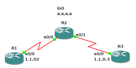
R1:
int s0/0
  ip address 1.1.0.1 255.255.255.0

R2:
int lo0
  ip address 100.0.0.2 255.255.255.255
int s0/0
  ip unnumbered lo0
int s0/1
  ip unnumbered lo0
ip route 1.1.0.1 255.255.255.255 s0/0
ip route 1.1.0.3 255.255.255.255 s0/1

R3:
int s0/0
  ip address 1.1.0.3 255.255.255.0
ip route 0.0.0.0 0.0.0.0 1.1.0.2
Even though R1 and R3 are not on the same segment they are able to reach each other. R1 and R3 think that this is just one big happy /24 switched network, even though R2 is actually routing between the two /32s. Because R3 also has a default route pointing to the (nonexisting) 1.1.0.2 it’s able to reach all other networks that R2 has routing to, like 100.0.0.2. It will not be able to ping its default gateway 1.1.0.2 though, since no router has that address configured on any interface. The address 1.1.0.2 is only used to choose the outgoing interface. No L2 destination address lookup is needed.
R1#show ip cef 1.1.0.3 detail
1.1.0.0/24, version 12, epoch 0, attached, connected, cached adjacency to Serial0/0
0 packets, 0 bytes
  via Serial0/0, 0 dependencies
    valid cached adjacency
R2 was just one router in this example, but it could just as well have been a string of a hundred routers, connecting R1 and R3. R2 just routes between /32s.